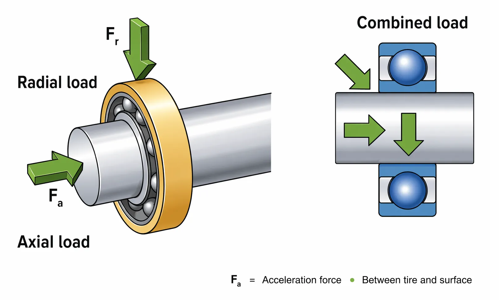
Bearing load direction helps narrow bearing selection fast. Radial load bearings handle forces perpendicular to the shaft, while axial load bearings handle thrust forces along the shaft. For combined loads, correct bearing type and mounting are critical for life and reliability.
Axial Load vs Radial Load: What’s the Difference?
Axial load acts parallel to the shaft (thrust), while radial load acts perpendicular to the shaft. Bearing selection by load type depends on which direction dominates, plus speed, stiffness, and misalignment. In real machines, combined loads are common, requiring bearings designed to carry radial and axial components simultaneously.
Video Guide: A clear visual explanation of axial vs. radial load directions and why direction matters to component selection.
Bearing load direction and the simplest mental model
Radial load tries to “bend” the shaft; axial load tries to “push/pull” the shaft along its centerline. The same bearing may tolerate a small amount of the other direction, but its geometry usually favors one primary direction.
- Radial load bearing (typical use): belt drives, gear meshes, rotor weight, overhung loads
- Axial load bearing / bearing for thrust load (typical use): screw drives, vertical shafts, propellers, helical gears, pump thrust
- Combined load bearings: angled contact designs or tapered geometries where contact lines can resolve both components
Haron Bearing Pro Tip: When you’re unsure, sketch the free-body diagram and label forces relative to the shaft centerline—90% of “wrong bearing” issues start with misidentifying the load direction, not with a catalog mistake.
Axial Load vs Radial Load: How Do They Differ?
Bearings “work” by transferring loads through rolling contacts whose angles determine which load components they can carry. Radial designs place contact roughly normal to the shaft, while thrust-capable designs create a contact angle that resolves axial force into the rolling elements and raceways. Combined load bearings deliberately use this angled geometry.
Video Guide: Demonstrates how ball bearings react under combined radial/axial loads and why contact angle changes capacity.
Contact angle is the core mechanism
Load direction capability is mainly governed by contact angle and raceway geometry. As axial load increases, the load zone shifts and stress concentrates differently than with pure radial loading.
- Radial loading: rolling elements load the lower (or load-side) zone; life depends on radial dynamic rating and load distribution.
- Axial loading: load is carried through an angled path; thrust capacity depends on contact angle and shoulder strength.
- Combined loading: the bearing sees a vector sum; equivalent dynamic load (P) increases nonlinearly, reducing calculated life.
- Mounting/preload: too little preload can cause skidding; too much raises heat and reduces life—especially at high speed.
Haron Bearing Pro Tip: If your application has meaningful axial force, treat “equivalent dynamic load” as a design gate—customers often underestimate how a modest thrust component can cut L10 life dramatically.
What factors affect bearing selection?
Bearing selection is driven by load magnitude and direction, speed, required life, stiffness, and allowable misalignment. Environment (contamination, temperature), lubrication method, mounting fits, and shaft/housing rigidity often decide whether a ball bearing axial load solution is acceptable or whether a roller bearing radial load design (or paired bearings) is required.
Video Guide: Walks through bearing sizing for life, connecting load, rating, and expected service life.
Practical selection checklist used in bearing engineering basics
Use this list to avoid “catalog-only” selection and capture the system effects that cause early failures.
- Load case definition: radial, axial, or combined; include transient peaks and duty cycle.
- Speed and heat balance: higher speed favors lower friction (often ball bearings) and careful lubrication.
- Required life and reliability: translate to L10 bearing life (L10/L10h) targets and select dynamic rating accordingly.
- Stiffness and runout needs: rollers often provide higher stiffness; precision classes may be required.
- Misalignment tolerance: self-aligning options or spherical geometries if shaft/housing deflection exists.
- Space constraints: bore/OD/width and shoulder heights can force certain series.
- Environment: contamination, corrosion, washdown, electrical pitting risk, temperature limits.
- Mounting and fits: interference fits, axial location method, thermal growth, preload/endplay.
Haron Bearing Pro Tip: I always ask for the “worst 10 seconds” load case—startup, tool engagement, or clog events often dominate bearing damage even if the average load looks safe.
What happens if the axial load is too high?
Excessive axial load overloads the raceway contact, raising stress, heat, and wear, and can quickly trigger spalling, cage damage, or smearing—especially if the bearing is primarily a radial type. It can also force the shaft axially, causing preload spikes, seal damage, and misalignment that accelerates failure.
Video Guide: Explains combined axial and radial loading effects and how thrust components change bearing loading and life.
Typical failure modes when thrust exceeds design intent
Axial overload often shows up as rapid temperature rise and thrust-direction surface distress.
- Early fatigue (spalling): localized high contact stress on race shoulders/raceways
- Cage distress: instability and pocket wear from skewing or skidding
- Smearing/scuffing: inadequate film thickness under high sliding components
- Loss of internal clearance: thermal expansion or axial displacement creates unintended preload
- Secondary damage: seals, couplings, gears, and housings suffer from axial movement
Haron Bearing Pro Tip: If axial load is uncertain, don’t “hope” a deep-groove ball bearing will handle it—use a bearing designed for thrust or a paired arrangement, and verify housing shoulders and locknuts can actually react the thrust.
What is the difference between axial and radial bearing load?
Radial bearing load is perpendicular to the shaft and primarily challenges bending support and radial stiffness. Axial (thrust) load is parallel to the shaft and primarily challenges shoulder support, contact angle, and axial location. Many bearings can carry both, but their allowable axial-to-radial ratio and life impact differ by design.
Video Guide: Shows how combined loading is modeled and why separating radial vs. axial components matters for design calculations.
Load comparison you can apply on a drawing
A quick comparison helps prevent selecting a “radial-only” solution for a thrust-dominated case.
| Aspect | Radial load | Axial (thrust) load |
|---|---|---|
| Direction vs. shaft | Perpendicular | Parallel |
| Typical sources | belts, spur gears, rotor weight | helical gears, screws, vertical shafts |
| Common bearing types | cylindrical roller, deep-groove ball | thrust ball, thrust roller, angular contact pairs |
| Typical sensitivity | misalignment, shaft deflection | shoulder strength, preload/endplay control |
| Common symptom when overloaded | raceway spalling on load zone | shoulder distress, rapid heat, axial displacement |
Haron Bearing Pro Tip: If you see helical gears or screw drives, assume axial load exists until proven otherwise—designers often model torque correctly but forget the thrust component created by helix angle or lead.
Key Features & Comparison
Choosing between axial load bearing, radial load bearing, and combined load bearings comes down to dominant load direction, needed stiffness, and speed. Ball bearing axial load capability is usually limited unless contact angle is designed for it, while roller bearing radial load designs excel in stiffness and capacity. Combined-load solutions trade complexity for reliability.
Feature-by-feature bearing load comparison for selection
Based on our internal data and market analysis, here is the breakdown:
| Selection factor | Radial-focused bearings (e.g., cylindrical roller) | Axial-focused bearings (e.g., thrust roller/ball) | Combined load bearings (e.g., angular contact, tapered roller) |
|---|---|---|---|
| Best at | High radial capacity, stiffness | High thrust capacity | Mixed radial + axial loads |
| Speed capability | Medium (varies by design) | Low–medium (often heat-limited) | Medium–high (angular contact can be high) |
| Misalignment tolerance | Low (unless spherical) | Low | Low–medium (depends on arrangement) |
| Typical mounting | Needs axial location elsewhere | Must be positively located and aligned | Often used in pairs/back-to-back or single tapered sets |
| Common risk | edge loading if misaligned | shoulder distress, lubrication starvation | incorrect preload/endplay, wrong arrangement |
| Good fit for | gearboxes, conveyors, heavy rotors | screw jacks, vertical pumps, turntables | machine tool spindles, helical gear shafts, pumps |
Haron Bearing Pro Tip: For combined loads, the “arrangement” is as important as the bearing—back-to-back vs. face-to-face pairing changes stiffness, misalignment behavior, and how thermal growth affects preload.
Cost & Buying Factors
Bearing cost is shaped by type (ball vs roller vs thrust), precision class, sealing, material, and whether you need a paired set for combined loads. The lowest purchase price often becomes the highest operating cost when axial/radial load assumptions are wrong, leading to rework, downtime, and secondary shaft/housing damage.
What to price and specify for an industrial load bearing guide purchase
- Bearing type and series: deeper sections, angular contact, tapered, thrust designs change cost significantly.
- Precision class (P0/P6/P5/P4): higher precision raises price and may require better shafts/housings.
- Seals/shields and grease fill: reduce contamination risk but add drag/heat at speed.
- Material and heat treatment: corrosion-resistant or high-temp steels increase cost.
- Matched sets and preload grade: essential for many combined load bearings; impacts lead time and price.
- Supplier documentation: load ratings, clearances, traceability, and QA certificates.
Haron Bearing Pro Tip: When comparing quotes, I ask suppliers to state the internal clearance/preload class and the exact sealing/lube specification—two bearings with the same part number prefix can behave very differently in axial load and temperature.
Conclusion
Separating axial load vs radial load is key to bearing selection. Choose radial, thrust, or combined load bearings based on real force direction and peaks. Verify equivalent dynamic load, mounting, and duty cycle for reliable performance.