
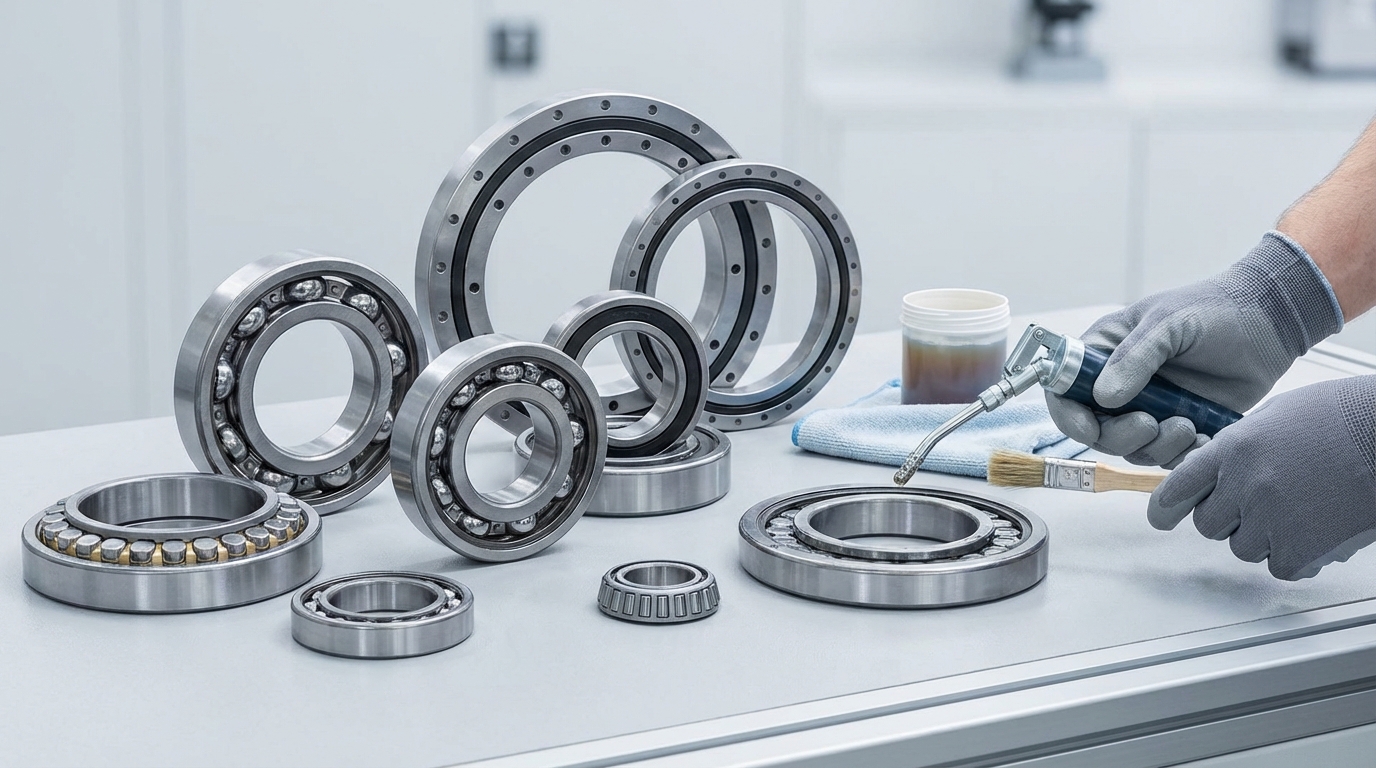
Robot bearings are precision rolling elements (cross-roller, angular contact, thin-section, etc.) designed to carry combined loads while maintaining stiffness, accuracy, and low torque in robot joints. A practical robot bearing selection process balances load/moment, required positioning accuracy, speed/acceleration, available envelope, and contamination control to maximize repeatability and service life.
Working Principle, Types, and Where They’re Used (Selection Guide)
Robot joints typically impose combined loads (radial + axial + overturning moment) with frequent direction reversals. The bearing’s internal geometry (contact angle, roller orientation, ring stiffness) defines how it supports these loads and how much elastic deflection (tilt) appears at the flange—directly impacting robot repeatability.
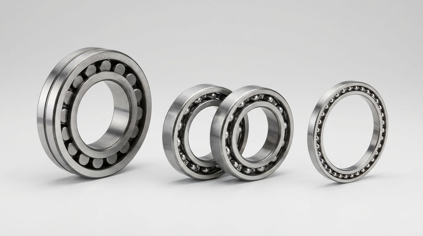
Common robot bearings types (quick comparison):
| Robot bearing type | Best at | Typical robot applications | Key design notes |
|---|---|---|---|
| Cross-roller (CRB) | High moment stiffness in compact size | RV/harmonic output bearings, shoulder/elbow/wrist joints | One bearing can take radial/axial/moment; preload controls backlash & torque |
| Angular contact ball (ACBB, paired) | High speed + axial load handling | Servo-driven joints, reducers with separate output support | Often used in DB/DF pairs; contact angle selection matters |
| Thin-section (4-point/ACBB) | Tight space + low mass/inertia | Wrist/end-effector, compact joints | Lower stiffness than CRB at same OD; housing stiffness becomes critical |
| Deep groove ball | Economy + moderate speed | Auxiliary axes, light-duty joints | Limited moment capacity; usually needs spacing/dual bearings |
| Tapered roller (paired) | High stiffness + axial loads | Larger articulated axes | More friction; sensitive to setup/preload |
| Needle roller | High radial load in limited radial space | Gearbox internals, support rollers | Needs hardened raceways; weak on axial/moment without extra elements |
A practical “robot bearing selection” checklist (what we size first):
- Load set: radial/axial + overturning moment at the joint output (worst-case pose).
- Stiffness target: allowable tilt/deflection vs repeatability requirement.
- Speed/acceleration: DN/NDm limits, heat generation, cage choice.
- Friction/torque: starting torque + torque ripple (critical for torque-controlled robots/cobots).
- Space & mounting: ring thickness, flange patterns, fit class, housing rigidity.
- Environment: sealing, corrosion, particulate, grease life, washdown.
- Life & reliability: L10 life with duty cycle + shock factors.
Haron Bearing Pro Tip: In our lab tests at Haron Bearing, we found that many “bearing failures” in robot joints are actually system stiffness problems—thin housings or uneven clamping distort rings, raising torque and edge-loading. We routinely validate ring roundness under bolt-up and recommend controlled preload plus flange flatness checks to protect precision.
How does Robot Bearings: Types, Applications, and Selection Guide work?
It works by mapping your joint’s combined load case (radial/axial/moment), precision target (tilt and runout), and operating profile (speed, duty cycle, contamination) to the bearing geometry that best supports it—then finalizing preload, fits, lubrication, and sealing so stiffness and torque stay stable over the robot’s life.
Selection workflow (engineering process)
- Define the joint: reducer type, output flange, mounting constraints, allowable torque.
- Convert loads: compute equivalent dynamic load and moment load at bearing center.
- Pick architecture: CRB vs paired ACBB vs thin-section based on stiffness/space.
- Choose preload: light/medium/heavy depending on stiffness vs torque limits.
- Set fits: interference/transition fits to avoid creep without distorting rings.
- Confirm limits: speed, temperature, grease life, sealing drag.
- Prototype test: torque ripple, temperature rise, repeatability under duty cycle.
Haron Bearing Pro Tip: Our technicians often see joint designs that size the bearing only by “static load,” ignoring moment + housing compliance. We always back-calculate tilt at the tool center point (TCP) and then tune preload and flange thickness so the bearing’s stiffness is actually realized in the assembly.
Benefits of using Robot Bearings: Types, Applications, and Selection Guide
Using a structured robot bearing selection guide reduces trial-and-error, improves repeatability, and prevents oversizing that increases motor torque and heat. You get clearer tradeoffs between cross-roller stiffness, angular contact speed capability, and thin-section packaging—leading to longer grease life, lower torque ripple, and more predictable maintenance intervals.
Key benefits (what improves in the robot)
| Benefit | What changes in practice | Typical outcome |
|---|---|---|
| Higher stiffness | Better moment support + controlled preload | Lower deflection, better path accuracy |
| Lower friction | Correct bearing type + grease + seals | Improved force control, lower motor heating |
| Longer life | Proper load rating + contamination control | Fewer early failures, stable torque |
| Easier sourcing | Defined specs + standardized series | Faster BOM approval and scaling |
Haron Bearing Pro Tip: Our technicians often see “precision” problems solved by switching to a higher-grade bearing, when the real lever is preload stability over temperature and time. We select grease and preload together to minimize torque drift in torque-controlled joints.
Maintenance tips for Robot Bearings: Types, Applications, and Selection Guide
Robot bearing maintenance focuses on keeping lubrication stable and contaminants out while monitoring torque rise, noise, and temperature. Use the correct grease fill and relube interval for your duty cycle, check seal integrity, and avoid aggressive washdowns that drive water into joints. Trending motor current is an effective early indicator of bearing drag changes.
Practical maintenance checklist (field-ready)
- Torque/current trend: set baseline after commissioning; alarm on drift.
- Grease management: correct type (base oil viscosity, thickener), correct fill, avoid mixing.
- Seal inspection: replace worn lips; verify labyrinths aren’t packed with debris.
- Fastener torque: re-check flange bolts; uneven clamp can distort rings.
- Vibration/noise: periodic acoustic/vibration checks for spalling signatures.
- Storage/handling: keep bearings sealed, clean, and corrosion-protected.
Haron Bearing Pro Tip: Our technicians often see premature wear caused by grease incompatibility (mixed thickeners) after service. We label each joint with grease spec and purge procedure, and we recommend switching grease only with a full clean-out and validation run to confirm torque stability.
What are your wholesale price tiers and lead times for robot bearings by type (cross-roller, angular contact, thin-section)?
Wholesale pricing depends on size, precision grade, preload, material, and whether flanged/custom rings are required. As a guideline, cross-roller units typically have higher cost and longer lead time than angular contact pairs, while thin-section bearings can vary widely by section and tolerance. We offer tiered discounts by annual volume and blanket orders.
Typical wholesale tiers & lead times (guideline ranges)
| Type | Common MOQ (pilot) | Volume tiers (discount vs list) | Typical lead time* |
|---|---|---|---|
| Cross-roller (CRB) | 10–30 pcs | 100+/500+/2000+ | 4–6 weeks standard; 8–12 weeks for high precision/custom |
| Angular contact (ACBB, matched pairs) | 20–50 pcs | 200+/1000+/5000+ | 3–5 weeks standard; 6–10 weeks matched/high-grade |
| Thin-section | 20–50 pcs | 200+/1000+/5000+ | 5–7 weeks standard; 8–14 weeks special sections/materials |
*Lead times assume normal raw material availability and standard coatings. For flanged rings, special seals, or corrosion-resistant steel, lead time can extend.
Haron Bearing Pro Tip: Our technicians often see procurement delays caused by incomplete specs—especially preload class and runout requirements. We shorten lead time by locking the drawing pack early (fits, flange flatness, bolt circle, preload/torque window) and then offering a blanket order with scheduled releases.
How do you recommend selecting robot bearings for high-precision joints (load, speed, torque, contamination), and can you provide compatible part numbers?
For high-precision robot joints, start with the dominant load case (especially overturning moment), then set a stiffness/tilt target and allowable friction torque window. Choose cross-roller for maximum stiffness in one bearing, angular contact pairs for higher speed, and thin-section where envelope is tight—then add sealing and grease tailored to contamination risk.
Selection matrix + “compatible” series examples (not a one-to-one interchange)
1) Choose by dominant requirement
| Requirement | Preferred type | Why |
|---|---|---|
| High moment, high rigidity, compact | Cross-roller | Single bearing carries combined loads with high stiffness |
| Higher speed, moderate moment, low heat | Angular contact (DB pair) | Better for speed; preload tunable; lower torque than many CRBs |
| Ultra-compact, low inertia | Thin-section (AC/4-point) | Packaging efficiency, lighter moving mass |
2) Contamination strategy (robot joints)
- Clean room / light dust: contact seals + low-torque grease.
- Metal dust / abrasive: labyrinth + contact seal combination; consider positive pressure.
- Washdown / humidity: corrosion-resistant materials/coatings + water-resistant grease; avoid pressure jet at seals.
3) Part-number guidance (series-level compatibility) Because robot joint bearings vary by OD/ID/width, flange pattern, preload, and precision, “compatible part numbers” are best provided after confirming your envelope and loads. As reference, we commonly cross-quote against these industry series families:
- Cross-roller: RA / RB / RU-style series (including integrated ring types)
- Thin-section: 67 / 68 / 69 thin-section families; 4-point contact thin-section variants
- Angular contact: 70 / 72 series (matched DB pairs; specific contact angles)
If you share ID/OD/width, required runout, preload/torque window, max speed, moment load, we can recommend exact Haron equivalents (e.g., HR-CR series for cross-roller; HR-TS for thin-section; HR-AC matched sets) and provide a drawing-to-drawing comparison.
Haron Bearing Pro Tip: Our technicians often see high-precision joints fail acceptance due to torque ripple, not load rating. We always specify a torque window at 20°C and after thermal soak, then tune preload, cage, and grease to keep friction stable under micro-oscillation (typical in robot wrists).